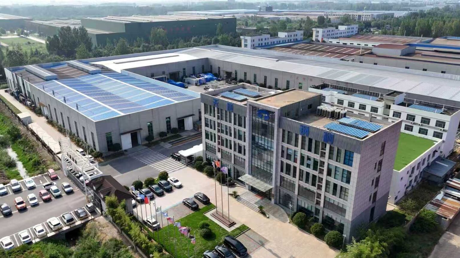
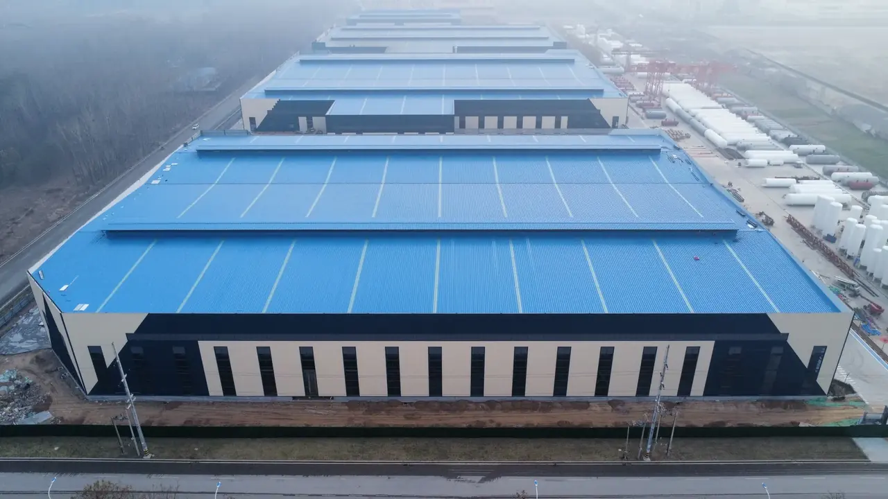
A steel structure factory layout should start with production flow, working space, and safe access. Mark fixed equipment and clear routes before choosing a column grid. Then ask the design team to test frame options against those needs.
The aim is a layout that supports the work inside the building. A neat frame plan can still leave poor routes for goods, maintenance, and future changes. Therefore, review the working layout before treating the steel outline as fixed.
For a large steel structure factory building, involve the process team, equipment vendors, site team, and structural engineer early. Each sees a different set of constraints. A shared plan makes those constraints visible before drawings move into detailed design.
Start the steel structure factory layout with production flow
First, map what enters the building and where it leaves. Trace one product family through receipt, storage, processing, checks, packing, and dispatch. Also show how waste, empty pallets, and returned goods leave the work area.
This map should reflect a real working day. For example, deliveries may arrive while finished goods wait for loading. If both use the same space, the plan needs a clear way to manage that overlap.
Draw routes before drawing columns
Use separate lines for staff, forklifts, long loads, and maintenance access. Then mark crossings and areas where vehicles must reverse or turn. A direct route for goods may create a difficult crossing for workers.
For general planning context, OSHA’s material handling rule addresses safe clearances and clear, marked routes. That is a US rule, rather than a universal aisle design guide. Your local safety team must confirm the rules and clearances for the actual site.
Also check routes outside the walls. A well-placed door may still face a tight yard or a steep approach. Add truck routes, waiting areas, and unloading points to the plan.
Space between work steps often becomes storage by default. Therefore, give raw stock, work in progress, and finished goods their own marked areas.
Ask the production team which buffers are essential and which could change. Also show the peak expected use rather than only the average shift. This helps the project team see where a narrow space may become a daily constraint.
Keep the first map simple enough to discuss. Its purpose is to test the flow, not to provide a finished construction drawing.
Define equipment envelopes and working clearances
A machine outline shows only part of the space it needs. Operators, guards, feeds, tool changes, and maintenance tasks may extend beyond that outline.
Therefore, ask each equipment vendor for the relevant layout data. Keep its issue date and revision beside the equipment reference. A copied plan from an older machine may not describe the unit you will buy.
Separate fixed footprints from access zones
Show the installed footprint with one boundary and the access zone with another. Also mark doors, covers, panels, and moving parts that need room to open.
Use a clear status for each piece of data. The following table can guide the layout review without setting any generic clearance values.
| Equipment input | Question to settle |
|---|---|
| Installed footprint | Which vendor drawing defines the machine outline? |
| Operator space | Where must staff stand and move during normal work? |
| Service access | Which parts need routine access or full removal? |
| Material feed | What length and route must the incoming stock use? |
| Replacement route | Can the largest removable part reach an exit? |
| Load interface | Who confirms support, anchorage, and foundation needs? |
For example, a service cover may open into a planned forklift route. Moving the machine slightly may solve that conflict before the frame layout becomes fixed.
Check the vertical space as well
Next, add a section through the busiest work zone. Show machines, lifted loads, ducts, lights, pipework, and the lowest structural depth.
Eave height does not describe every clear height inside the building. A roof haunch or low service route may govern the space above a machine. Therefore, state the clear level the operation needs at that position.
If overhead cranes are planned, use the crane vendor’s data. Ask the engineer to check travel, hook coverage, maintenance access, and structural interfaces. Crane capacity alone cannot settle those questions.

Test column grids against the working plan
Once the team understands the work zones, it can assess frame options. The best column arrangement depends on both the process and the structural scheme.
Do not assume that the widest clear span always gives the best project result. Also do not assume that the lightest frame gives the lowest total cost. Test how each option affects the use of the floor.
Mark zones where columns can and cannot stand
First, distinguish fixed limits from preferences. A production line may need a clear route, while a storage area may accept a column.
Give the design team enough room to suggest options. However, require each option to show the same equipment layout and traffic routes. Otherwise, a cheaper frame may simply move a problem into the operation.
Use a short comparison sheet for each steel structure factory layout option.
| Review item | What to compare |
|---|---|
| Production route | Does the option preserve the required flow? |
| Usable floor | Which spaces become difficult to use? |
| Working height | Are the stated clear levels maintained? |
| Crane coverage | Can the crane serve the required work zones? |
| Civil interface | What changes at bases and equipment foundations? |
| Future work | Which later changes remain possible? |
Ask the team to explain its choice in words as well as drawings. That record helps new team members understand why a particular grid was chosen.
A column centreline does not show every item that uses floor space. Base details, bracing, guards, and adjacent services also need attention.
Check wall bracing against doors, access panels, and future openings. Then ask the engineer to review any proposed change to the bracing arrangement. Moving a brace is not simply a layout edit.
Also compare the steel grid with the civil layout. Foundations and machine bases may compete for space below the floor. Resolve those interfaces with the relevant designers before releasing construction information.
Coordinate services, expansion, and site access
Industrial steel buildings need space for systems beyond the main frame. Ventilation, power, water, fire services, and maintenance routes all affect the working plan.
Therefore, reserve service zones early, even when the detailed design is still developing. State which routes are fixed and which can move after review.
Plan service routes and access together
A clear overhead zone can become crowded once several teams add their systems. Ask each team to show both its equipment and the access needed to inspect it.
Also check where services cross doors, crane paths, or roof openings. One drawing should show these shared interfaces. Each discipline can then confirm its part against the same view.
For an early review with TCGG, provide the working layout and list the unresolved interfaces. Ask which inputs the proposed steel package needs before further design. Do not assume the steel supplier also owns every service design task.
Use the manufacturing workflow to discuss the drawing inputs needed by the shop. The same principle applies to roof equipment and suspended items. Show their proposed positions, and have the design team confirm the support needs.
Give future expansion a defined direction
If expansion is likely, describe what the next phase may contain. More production space, a new crane bay, and a loading extension create different questions.
Then test the edge of the first phase. Check walls, doors, drainage, service routes, site roads, and potential construction access. An apparently open boundary may still have several fixed obstacles.
Treat future capacity as a design question, not a general promise. The engineer should state what the current scheme allows and what would need fresh review.
Release the layout through clear review steps
A useful layout review ends with decisions and an updated drawing. It should not leave several conflicting versions in use.
First, give the steel structure factory layout a revision number and date. Then identify who can approve changes to process routes, machine positions, and the steel grid.
Hold a focused layout review
Walk through the building in the order the goods will move. Then repeat the review from the viewpoints of maintenance, staff access, and site delivery.
Use the following checks to keep the meeting concrete:
- Trace goods from receipt to dispatch without skipping buffer areas.
- Check the access zones around each fixed machine.
- Review column and bracing positions against working routes.
- Show the lowest clear level in critical sections.
- Confirm the crane and service interfaces still awaiting design.
- Test how large equipment will enter and later leave.
- Record the assumptions behind each future expansion area.
For each open point, name an owner and a required next action. Also note which design step depends on that answer. This keeps minor open choices from blocking unrelated work.
Test one real work route before release
Consider a long part that enters through a side door. It must turn, reach a machine, and leave for the next work step. Draw that path with the handling unit and its load, rather than with a thin arrow alone.
Now add the column bases, guards, service panels, and a load waiting for the same machine. If the route fails, compare a door move, a machine move, and a revised column zone. Ask the design team to check the structural effect of each option.
The Panjin forging facility project shows why a crane hall needs more than a floor outline. Its published project record lists several crane ratings and a heavy steel frame. Those facts describe that project, not a standard layout for every new factory.
Before applying a similar idea, compare your crane data and process needs. The industrial building planning page groups layout, equipment, and site inputs for that discussion. Use it to assemble the inputs, rather than to choose a frame without design review.
The fabricated component overview also helps explain what may occupy a column or beam interface. Check those details on the actual drawing before you freeze a work route.
Control changes after the review
When an input changes, update the shared layout and explain the effect. A machine move may affect more than the nearest column.
Send the change to the relevant process, structural, civil, and service teams. Then record whether each team needs to revise its work. Avoid relying on an informal message as the only change record.
The outcome should be one agreed layout basis with a visible list of remaining questions. That gives detailed design a clear starting point. It also helps the project team judge later changes against the original operating needs.
Need help reviewing your factory layout before detailed design? Send us an inquiry with your process plan and equipment drawings. Our team will reply and help clarify the next inputs.